Specifications for optical surfaces outline the precise quality criteria that govern the performance of optical components such as lenses and mirrors. These criteria encompass parameters like surface roughness, flatness, curvature, and coatings. Understanding these specifications is crucial to ensure optimal light transmission, image quality, and system efficiency in various applications, from microscopy to astronomy. Accurate adherence to specifications ensures minimal aberrations, reflections, and scattering, leading to enhanced overall optical performance.
The ability to comprehend optical surface specifications empowers you to make informed decisions, ensure performance, and contribute effectively to the advancement of optical technology.
Surface Quality
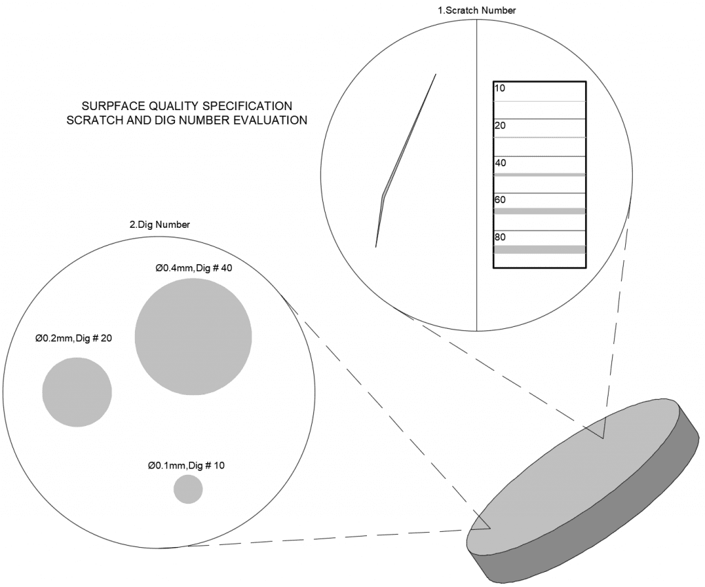
The characteristics of an optical surface’s appearance fall under the term “surface quality.” This encompasses attributes like scratches, pits, and digs. In most cases, these defects are primarily cosmetic and have minimal impact on system performance. However, they can lead to a slight reduction in system throughput and increased scattered light. Some surfaces are more susceptible to these effects, such as (1) image plane surfaces where defects are in focus and (2) high-power surfaces where defects can cause energy absorption and optic damage. The scratch-dig specification, defined by MIL-PRF-13830B, is the common metric for surface quality. The scratch component compares surface scratches to standardized scratches under controlled lighting, while the dig component quantifies small pit dimensions. Scratch-dig ratings like 80-50 (standard quality), 60-40 (precision quality), and 20-10 (high precision quality) are typically used.

Surface Flatness
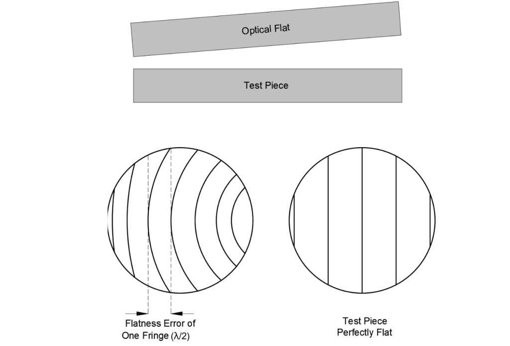
Surface flatness pertains to the accuracy of flat surfaces like mirrors, windows, prisms, and plano-lenses. Optical flats, high-quality reference surfaces, are used to gauge flatness deviations in test pieces. Placing the test optic against an optical flat reveals interference fringes, indicating the flatness of the test surface. Even, straight, and parallel fringes suggest that the test surface matches the reference flat. Curved fringes indicate flatness errors, measured in wavelengths (λ). One fringe corresponds to half a wave. The typical grade is 1λ flatness, precision grade is λ/4 flatness, and high precision grade is λ/20 flatness.
Flatness is often applied to features of size. This means that the flatness requirement is applicable to the surface when the part is at its specified size.
Flatness can be affected by a number of factors, including the manufacturing process, the material used, and the environmental conditions.
It is important to inspect flatness on a regular basis to ensure that the parts meet the requirements.

Surface roughness
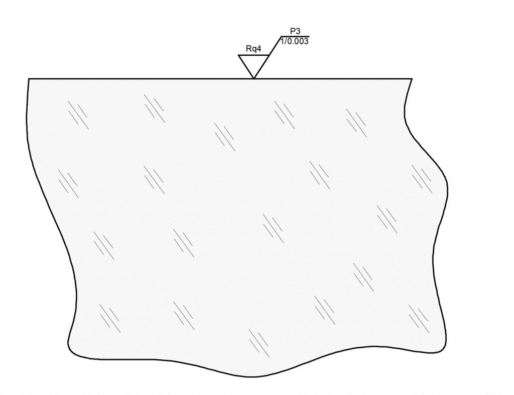
Surface roughness is a measure of the microscopic unevenness of a surface. It is quantified by the deviations in the direction of the normal vector of a real surface from its ideal form. If these deviations are large, the surface is rough; if they are small, the surface is smooth.
Surface roughness is affected by a number of factors, including the manufacturing process, the material used, and the environment in which the surface will be used. It can have a significant impact on the performance of a product, such as its wear resistance, friction coefficient, and ability to seal.

Polishing Grade Designation
Number, N, of Microdefects per 10mm of Sampling Length
P1
80 ≤ N ≤ 400
P2
16 ≤ N ≤ 80
P3
03 ≤ N ≤ 16
P4
N < 03
Surface Accuracy
Optical surface accuracy pertains to the variance between the actual and intended shape of an optical surface. This element holds immense significance within optical components and is conventionally quantified in wavelengths or fringes that correspond with the laser wavelength employed in the interferometer. The specification of anticipated surface accuracy is pivotal in avoiding additional wavefront distortions. Such distortions yield aberrations, subsequently diminishing the performance of the system.
Diverse methodologies are available for gauging optical surface accuracy. These encompass employment of test plates, laser interferometers, laser interferometers augmented with computer-generated holograms (CGHs), contact profilometers, and coordinate measuring instruments.
CGHs, which function as null lenses, can be seamlessly incorporated into the testing mechanism of an interferometer. This incorporation is particularly advantageous for scrutinizing intricate surfaces such as aspheric and freeform shapes. CGHs are frequently amalgamated with laser interferometers to effectively manage the surface accuracy during the polishing process of aspheric lenses. (See details for Optical Surface Accuracy)

Surface Power & Irregularity
Power concerns curved optical surfaces and their deviation from reference surfaces. Similar to flatness testing, interference fringes from air gaps are used to describe the deviation. This results in Newton’s Rings, with the number of rings reflecting the degree of deviation. The count of dark or light rings corresponds to twice the wave error count.
Irregularity describes deviations in surface shape from a reference surface. It’s derived from the same measurement as power. Regularity refers to the circular fringes’ sphericity formed during the test surface comparison. Detecting small irregularities becomes difficult when power exceeds 5 fringes. Common practice is to specify surfaces with a power-to-irregularity ratio around 5:1.

Surface Finish
Surface finish, or roughness, quantifies small-scale surface irregularities. It often results from the polishing process and can lead to faster wear and potential issues in applications involving lasers or heat. Manufacturing tolerances for surface finish vary 50Å RMS for typical quality, 20Å RMS for precision quality, and 5Å RMS for high quality.
Factory Standard
Surface Quality
60-40
Surface Flatness
PV<λ/4
Surface Roughness
Ra 0.012μm
Surface Accuracy
Power(IRR) 3(0.5)fringes
Please contact us if you’d like to schedule a consultation or request for a quote on your next project.
Related Content
GREAT ARTICLE!
Share this article to gain insights from your connections!

