
Key Takeaways
- Concave and convex mirrors are essential components in advanced optical systems, enabling precise beam control, compact imaging, and wide field-of-view designs.
- In high-power applications, thermal effects can alter mirror geometry and degrade performance, requiring careful material selection, cooling strategies, and multi-physics simulation. In ultra-wide-angle systems, convex mirrors support miniaturization but introduce stray light challenges that demand rigorous optical and mechanical design.
- Manufacturing specifications—such as surface figure, roughness, and tolerances—directly impact system performance, making integrated optical, thermal, and mechanical optimization critical for reliable, high-performance solutions.
Concave and convex mirrors are far more than simple demonstrations of geometrical optics. In modern optical systems, they serve as critical components for beam shaping, afocal imaging, and stray-light control—particularly in high-power lasers, space telescopes, and compact ultra-wide-angle sensors.
This article focuses on spherical mirrors from an engineering perspective, addressing key challenges such as aberration budgeting, thermo-mechanical coupling, and system miniaturization, while providing practical design insights for experienced optical engineers.
From Geometric Parameters to Engineering Tolerances
In optical design software and manufacturing documentation, fundamental mirror parameters extend beyond geometric definitions—they directly influence system performance and fabrication cost.
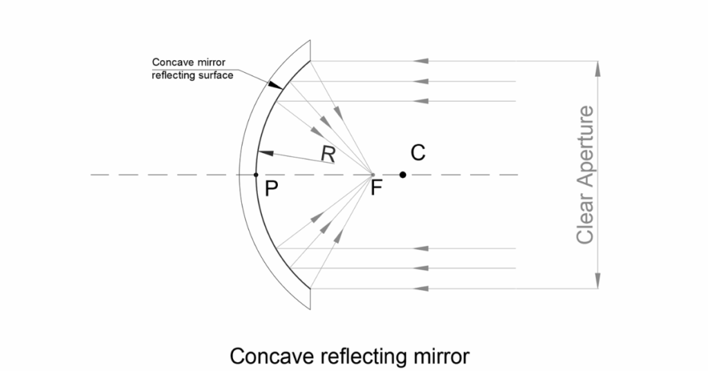
- Pole (P)
More than a reference point, the pole serves as the mechanical datum. In ray-tracing tools (e.g., Zemax, CodeV), it defines the global coordinate origin, anchoring all tilts, decenters, and tolerance analyses. - Center of Curvature (C) and Radius (R)
These define the paraxial focal length (f ≈ R/2) and underpin primary (Seidel) aberration calculations. Even minor variations in radius—due to manufacturing tolerances or thermal effects—can significantly impact wavefront error. - Aperture / Clear Aperture
The clear aperture determines the system’s numerical aperture (NA) and throughput, and governs vignetting behavior. Surface figure accuracy (RMS, PV) must be maintained across the entire usable aperture. - Focal Point (F)
While real for concave mirrors and virtual for convex mirrors, practical design emphasizes conjugate points, which define working distance and magnification.
Case Study I: Concave Mirrors in High-Power Laser Systems
Managing Thermally Induced Aberrations
Concave spherical mirrors are widely used in high-power laser systems due to their lack of chromatic aberration and high damage thresholds. However, at kilowatt-level average power, thermally induced aberrations become a critical design challenge.Engineering Challenge
A high-energy laser system used a 100 mm diameter concave copper mirror with a 500 mm radius of curvature as its final focusing element. After a short period of operation, the focal spot size increased significantly, accompanied by a severe drop in Strehl ratio.Root Cause
Thermal loading introduced a thermal lensing effect. Despite copper’s high thermal conductivity, radial temperature gradients caused non-uniform expansion. This resulted in a small but critical change in the radius of curvature (e.g., 500 mm → 500.1 mm), introducing higher-order spherical aberration that cannot be corrected by simple defocus.Engineering Solutions and Trade-Offs
- Substrate Material Selection: Thermo-structural finite element analysis (FEA) is essential. Materials such as Zerodur® or SiC offer significantly lower coefficients of thermal expansion (CTE) compared to copper, reducing deformation under thermal load—though at higher cost.
- Active or Passive Cooling: Efficient thermal management, such as micro-channel water cooling, is critical. Designs should ensure surface deformation remains within λ/10 (@632.8 nm), verified through simulation.
- Coating Strategy: High-reflectivity coatings deposited via ion-beam sputtering (IBS) minimize absorption, reducing thermal load at the coating interface.
Key Highlights
- Thermal deformation directly alters optical performance
- Optical–thermal–mechanical co-simulation is required
- Material and cooling design are primary control factors

Case Study II: Convex Mirrors in Ultra-Wide-Angle Systems
Balancing Miniaturization and Stray Light
Convex mirrors, with their negative focal length, are ideal for compressing fields of view and folding optical paths. They are widely used in automotive imaging, surveillance, and endoscopic systems. The primary challenge is achieving a wide field of view and high image quality within a compact system while controlling stray light.Engineering Challenge
A SWIR imaging system required:- 180° field of view
- F/1.2 aperture
- Total track length under 15 mm
Solution: Aspheric Convex Mirror Integration
- Aberration Control Convex mirrors introduce significant negative spherical aberration and coma. Aspherization enables compensation of field curvature and distortion across the system.
- System Miniaturization The convex mirror compresses the incoming field into a virtual image, enabling a compact reverse-telephoto configuration.
Stray Light Challenge (Critical)
Because the convex mirror directly faces external light sources, stray light paths can form:- Reflection from housing surfaces
- Secondary reflection from the mirror
- Unwanted illumination of the sensor
Engineering Countermeasures
- Non-Sequential Ray Tracing Use tools such as LightTools or FRED to simulate full 3D optical and mechanical interactions.
- Mechanical Design Optimization Implement baffles and knife edges to block ghost paths without reducing the usable field.
- Surface Treatment Apply ultra-black coatings and define BRDF models to minimize scattering and preserve signal-to-noise ratio.
Key Highlights
- Stray light control is as critical as imaging performance
- Mechanical and optical design must be co-optimized
- Simulation-driven validation is essential
Linking Manufacturing Specifications to System Performance
For technical buyers and system designers, every specification directly affects both performance and cost.
Typical parameters and implications:
- Diameter Tolerance (+0 / −0.1 mm)
Ensures proper mounting without inducing stress or deformation. - Surface Figure (λ/4 PV @ 633 nm)
Defines baseline imaging quality; higher precision (λ/10) is required for diffraction-limited systems. - Surface Quality (Scratch-Dig 40-20)
Critical for high-power applications, where surface defects can initiate damage. - Clear Aperture (>90%)
Guarantees usable optical area while accommodating mechanical mounting.
All parameters should be verified through interferometry, profilometry, and related metrology techniques.
Frequently Asked Engineering Questions
1. How should I choose between a concave mirror and a transmissive lens in high-power laser systems?
The decision depends primarily on thermal behavior and dispersion:
- Mirrors eliminate bulk absorption and chromatic dispersion
- Lenses introduce thermal lensing due to material absorption
- For high-power or multi-wavelength systems, mirrors are typically preferred
Final selection should be based on integrated optical–thermal simulation.
2. What are the most critical parameters for convex mirrors in ultra-wide-angle systems?
In order of importance:
- Aspheric coefficients – primary tool for aberration control
- Clear aperture to radius ratio – determines incident angle distribution
- Surface roughness and BRDF – directly impacts stray light and image contrast
Final Note
By combining real-world case studies, quantitative analysis, and system-level trade-offs, spherical mirrors can be understood not merely as optical elements, but as integrated components within complex engineering systems.


GREAT ARTICLE!
Share this article to gain insights from your connections!