Bandpass Filters
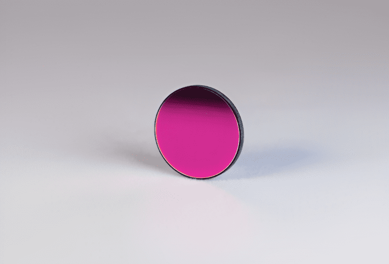
A bandpass filter will transmit a well-defined range of wavelengths of light while blocking all others. The width of the band transmitted can be as narrow as less than 1 nm or as wide as a few hundred nanometers. The choice of substrate and coatings used will determine which specific wavelengths of light are isolated and transmitted, and whether the filter works best for ultraviolet (UV), visible (VIS), or infrared (IR) applications. At Avantier, we design and manufacture custom bandpass filters for a wide variety of applications.
Applications of bandpass filters
Bandpass filters are found anywhere where it is desirable to transmit only a band of light, not the full spectrum. Some examples would be clinical chemistry instrumentation, immunoassays, fluorescence, color separation, flame photometry, elemental and laser line separation, spectral radiometry and environmental testing.


Bandpass Filters
Understanding bandpass filters
A bandpass filter may be as simple as a combination of a high-pass filter and a low-pass filter. Since a high pass filter only transmits light with a wavelength greater than a given cutoff (call this point a), and a low pass filter only transmits light lower than another cutoff (call this point b), the combination of the two will be a filter that allows light with a wavelength of greater than a but less than b.
Specifications of bandpass filters
Commonly used specifications for bandpass filters include peak transmission, center wavelength, full-width half-maximum, cut-on and cut-off wavelengths, pass band ripple, edge steepness and blocking.
- Peak transmission refers to the maximum transmission of the filter, and is usually given in percent. For instance, if a bandpass filter has 92% peak transmission 92% of the most freely transmitted light is passed through the filter.
- Center wavelength (CWL) refers to the middle of the transmitting region, and is given in nm. For instance, the center wavelengths of a bandpass filter that transmits over the region 520 to 544 might be 532. CWL is not necessarily the point with the peak transmission
- Full-width half-maximum tells us how wide the transmission region is at half maximum transmission value. For the narrow bandpass filter described above, the FWHM might be 1.20.
- Cut-on and cut-off wavelengths are another way of designating the edges of the filters transmitting region. They are also typically given in nm.
- Pass band ripple tells us how flat the transmitting region is. A bandpass filter may have a peaked pass band shape, or may have an approximately flat top.
- Edge steepness is another specification that tells us how steep the transition from blocking to transmission is.
- Blocking range tells us which wavelengths of light are blocked, and optical density tells us just how well the light is blocked. The optical density (OD) is measured by a log scale, which relates the transmitted to incident light.
Bandpass Filters at Avantier
If the terminology surrounding bandpass filters is confusing to you, don’t worry. The optical design team at Avantier can help you determine the types of filters that work best for your application and walk you through the entire design and manufacturing process. Whether you need a hard coated filter with a dielectric spacer built in, a standard Fabry Perot bandpass filter or a thin film interference filters for LIDAR, we can help you design your optical assembly, start a custom order and produce the perfect optical components for your filtering operation.
Contact us to set up an introductory consult and get the process started.
WE CAN HELP YOU!
Contact us NOW for sales & expert advice.

