Key Takeaways:
- Waveplates, also known as retarders, are optical components used to change the polarization state of light without affecting its intensity or direction.
- They work by introducing a phase delay between two orthogonal polarization components using birefringent materials like quartz.
- Key types include quarter-wave plates, half-wave plates, zero-order-waveplates, and achromatic waveplates, each serving different applications in optical communication, measurement, and display technologies.
- Precise control over waveplate thickness and orientation is crucial for achieving desired polarization effects in advanced optical systems.
Introduction to Optical Waveplates
Light is a form of electromagnetic wave with fluctuating properties. When light waves interact with matter during propagation, certain phenomena occur, one of which is polarization. Polarization refers to the selectivity of the direction of the electric field’s vibration within a light wave. According to the different polarization state of light, it can be divided into linear polarized light, circular polarized light, elliptically polarized light and so on. To change the polarization state, optical elements such as waveplates (or retarders) are commonly used.
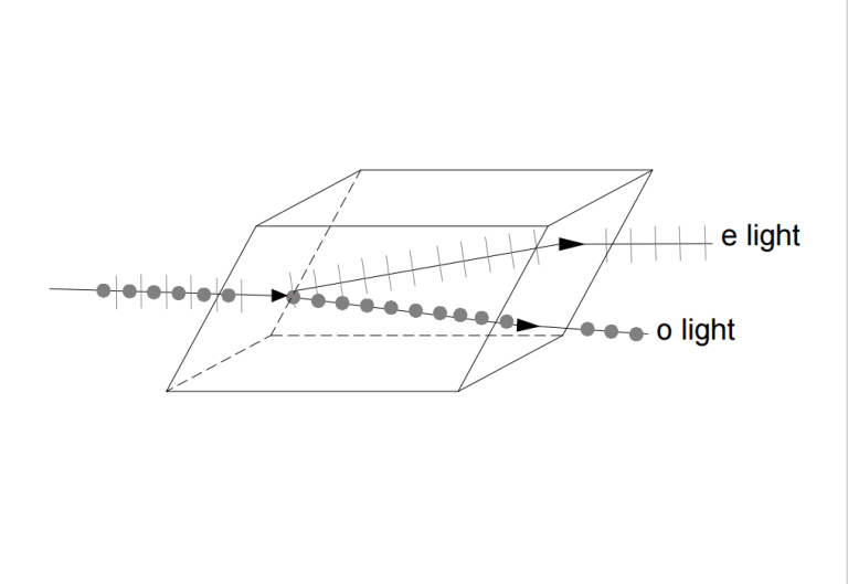
Waveplates, also known as retarders, are optical components designed to alter the polarization state of light as it passes through them, without affecting the beam’s intensity, direction, or position. Waveplates are transparent plates with a birefringent effect. Birefringence is a phenomenon in which light passing through certain crystals splits into two beams that are refracted in different directions and vibrate perpendicular to each other. Waveplates achieve this by inducing a phase delay between two orthogonal polarization components of the light. In the case of unpolarized light, a waveplate behaves similarly to a simple transparent window, allowing light to pass through with minimal interference. However, with polarized light, waveplates introduce complexities that require a deeper understanding of key concepts such as wave retardation, fabrication methods, and their various types and applications. By carefully selecting and orienting a crystal relative to its axes, a waveplate can be optimized to exhibit a minimal index of refraction for one polarization component of a linearly polarized wave.
The key parameter in waveplate functionality is retardation, which quantifies the phase shift between the polarization components along the fast and slow axes. This retardation is measured in degrees, waves, or nanometers, with one full wave of retardation corresponding to a 360° phase shift or a specific wavelength in nanometers. The precision of this phase shift, or retardation tolerance, is typically expressed in terms of degrees, fractions of a wave, or nanometers, depending on the application’s requirements.
A wave plate has a fast axis and a slow axis, both perpendicular to the surface and the direction of the beam propagation, and perpendicular to each other. Light that vibrates in different directions travels at different speeds in the wave plate. Therefore, the waveplate can induce an additional phase difference in the vertically vibrating light, thereby changing the polarization state of the light wave. This property has a wide range of applications in fields such as optical fiber communication and optical precision measurement.

Since waveplates utilize the birefringence effect of materials, they are usually made from crystalline substances. Examples of birefringent materials include calcite (CaCO3), magnesium fluoride (MgF2), sapphire (Al2O3), mica (a silica material), and some birefringent polymers. The most commonly used material is quartz crystal, which is a common mineral with high transmittance and a low scattering rate. Due to its good crystallization properties and hardness, quartz is ideal for processing high-quality glass slides.
The thickness of the wave plate determines the phase difference of the light, which in turn affects the polarization state. The thickness of the waveplate is typically achieved through precision machining, and strict control of thickness error is required during the manufacturing process.
Classification of optical waveplates
The most commonly used optical waveplates are quarter wave plates (¼ waveplates) and half wave plates (½ waveplates). When light normally incident through a specific thickness of the waveplate undergoes a birefringence effect, resulting in a phase difference equal to λ/4, it is referred to as a ¼ waveplate. Similarly, if the phase difference is equal to λ/2, such a slide is called a 1/2 waveplate. Both 1/4 waveplates and 1/2 waveplates can be classified as a true zero order waveplate, multiple waveplate, glued zero-order waveplate (composite waveplate), or an achromatic waveplate.
- Multiple order waveplate: In addition to achieving the designed ¼ wavelength or ½ wavelength delay, the optical path also passes through several full-wavelength delays. Multiple order waveplates are relatively inexpensive and can be used in applications where temperature and wavelength variations have less impact.
- Glued zero-order wave plate: A glued zero-order waveplate is composed of two multiple-order waveplates, with the fast axis of one waveplate aligned with the slow axis of the other, forming a composite delay plate. The net delay is the difference between the delay amounts of the two waveplates, resulting in either a ¼ wavelength or ½ wavelength delay.
- True zero-order wave plate: The delay function of a true zero-order waveplate is achieved by a single waveplate, which is challenging to process due to its thinness and is generally glued to a glass substrate. However, true zero-order waveplates offer low wavelength sensitivity, high temperature stability, and high delay accuracy, making their performance superior to that of other waveplates.
- Achromatic wave plate: A waveplate made from a single crystalline material can only meet the phase delay function for a specific wavelength. To achieve consistent phase delay across a certain band range, an achromatic waveplate is needed. Achromatic waveplates consist of two different materials, including crystals, which practically eliminate chromatic dispersion. Achromatic waveplates provide more precise retardation across broadband wavelength ranges.
Application of optical wave plates
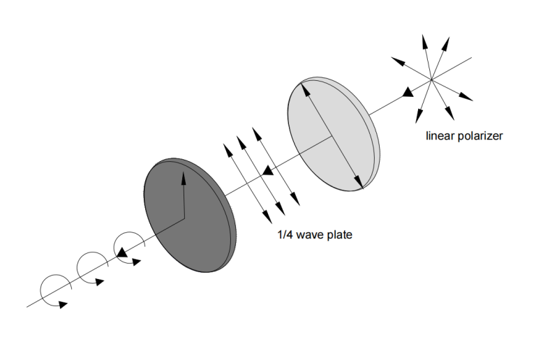
Wave plates are widely used in optical experiments, optical equipment and communication systems. For example, when linearly polarized light is incident on the 1/4 wave plate, with the polarization direction at a 45° angle to the fast and slow axes, the light is polarized along the fast axis. Due to the phase difference between the components along the fast and slow axes, circularly polarized light is produced upon exiting. By gluing a waveplate with a linear polarizer, a circular polarizer can be obtained, which is a typical application of using a waveplate to change the polarization state of light.

Waveplates can also be used to adjust and control light intensity, and to change and regulate the amplitude, phase, and frequency of the optical signal. In addition, waveplates play an important role in electronic displays, solar cells, optical sensors, and other applications.
Optical Isolation – A quarter-wave plate can be used in an optical isolator, a device designed to eliminate unwanted reflections. This device typically combines a quarter-wave plate with a linear polarizer or a polarizing beamsplitter cube.
Polarization Cleanup – In optical systems, multiple reflections from metal or dielectric mirrors are often necessary. When the beam hits the mirrors at a normal angle or when the plane of polarization aligns with or is perpendicular to the plane of incidence, the polarization state remains unchanged. However, if the polarization direction forms an angle with the plane of incidence, the reflection can cause a small phase shift between the parallel and perpendicular components, particularly with metal mirrors, which inherently have some loss. As a result, the reflected wave may become slightly elliptically polarized instead of linearly polarized. This can be detected by its reduced extinction when a polarizer is inserted and rotated. To correct this slight ellipticity, a full waveplate can be inserted and slightly tilted around either the fast or slow axis to adjust the retardation and cancel out the ellipticity.
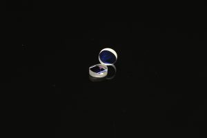
The following figure shows the real product of 1/4 wave plate and wave plate bonded with cylindrical lens.


To set up a waveplate for producing circularly polarized light, first use a polarizer to find the plane of polarization. Then, insert a quarter-wave plate between the source and polarizer, rotating it around the beam axis until the extinction is maintained. Next, rotate the waveplate 45° from this position. At this point, half of the incident light should pass through the polarizer. To verify the quality of the circular polarization, rotate the polarizer; if the light intensity remains constant, the polarization is circular. If there’s variation, the light is elliptically polarized, and you may need to slightly tilt the waveplate along its fast or slow axis while rotating the polarizer to achieve constancy.
Optimizing Light Polarization
Optical waveplates are essential tools for controlling and manipulating the polarization of light, with broad applications in fields such as optical communication, precision measurement, and electronic displays. By leveraging the birefringent properties of specific materials, waveplates allow for precise adjustments in the phase and polarization state of light, enabling advancements in both research and practical applications. Understanding the types, functions, and proper use of waveplates is crucial for optimizing their performance and achieving desired optical outcomes. As technology evolves, waveplates will continue to play a vital role in the development of sophisticated optical systems.
GREAT ARTICLE!
Share this article to gain insights from your connections!

