MTF Testing with TriOptics: Avantier utilizes TriOptics MTF Stations to measure the Modulation Transfer Function (MTF) of optical systems, ensuring accurate assessment of their performance.
Systematic Measurement: Avantier employs a systematic procedure involving collimators and CCD adjustments to precisely measure MTF across various spatial frequencies.
Optical System Analysis: Through MTF testing, Avantier gains deep insights into the true capabilities of optical systems, ensuring they meet stringent standards of contrast and sharpness.
Performance Evaluation: MTF plots and tables generated from testing provide comprehensive insights into the performance of optical systems, guiding improvements for enhanced clarity and resolution.
What is MTF?
Modulation Transfer Function (MTF) is a fundamental concept in optics and image quality assessment that quantifies how well a lens system is able to reproduce various spatial frequencies in an image.
It establishes the correlation between the output and input within an optical system and stands as the most comprehensive method for such an evaluation, it involves various parameters, including resolution, sensitivity, physical geometry, and noise. Alternatively expressed in cycles, lines, or line pairs per millimeter, MTF can be measured for both lens components and optical assembly.
What instrument is used to measure MTF typically at Avantier?
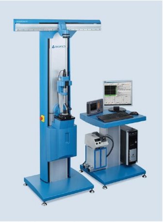
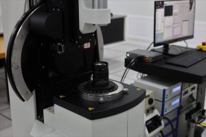
Avantier has ImageMaster® TriOptics MTF Stations in-house, with the capability to handle MTF testing, enabling the precise determination of the imaging quality of lenses and optical systems.
For further services, MTF testing data will be provided to the optical system and assemblies’ deliveries, and optical components upon request.
How is MTF measured?
With an in-house ImageMaster® HR MTF station, Avantier is able to provide an outstanding level of accuracy and flexibility in testing the MTF. Following is the common procedure to measure MTF for an optical lens assembly.
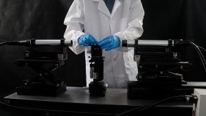
Step 1: Equip with collimators with different EFL (50mm/300mm/500mm), Avantier is available to measure according to different customers’ requirements.
Figure 1
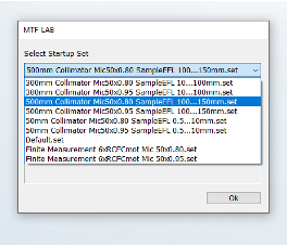
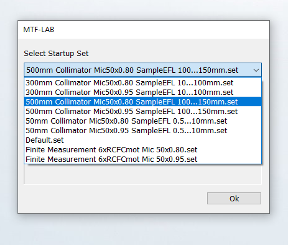
Step 2: Select whether the testing sample is an infinite or finite conjugate lens and focal length, enables to test on various lenses.
Figure 2
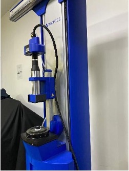
Step 3: Switch to the corresponding collimator when necessary. Connect the light source and stepper motor at the same time to set up.
Figure 3
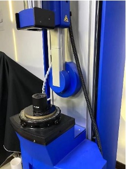
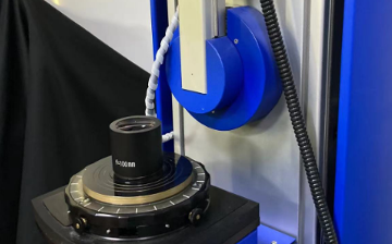
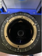
Step 4: Place sample lens in place, where above image plane, and beneath light source, while turning on stepper motor and light source.
Figure 4
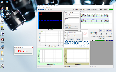
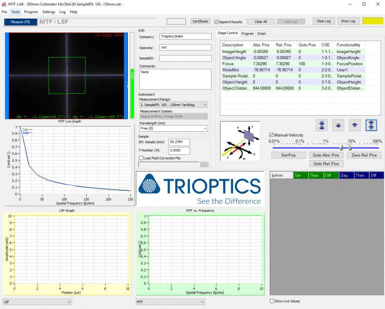
Step 5: Open TriOptics software, selecting corresponding mode and completing initialization.
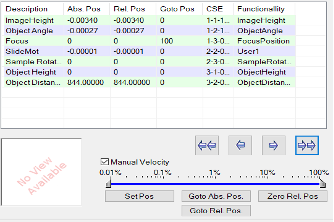
Step 6: Adjust the “Slide Mot” parameter to adjust the sample stand’s height, ensuring the entrance pupil of the sample lens in the center of the collimator’s swing arm.
Step 7: Adjust the “Focus” parameter to adjust CCD’s height. Based on BFL of the lens, it determines how close the CCD to the image plane.
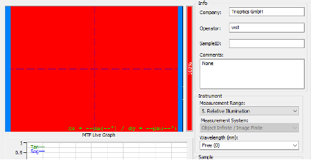
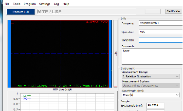
Step 8: Under “Relative Illumination” button, adjusting “Focus” parameter and sample position to ensure that CCD is on image plane, and receives the generated image. As examples shown, if the image is black representing no energy is received at this position, operator needs to re-adjust, until the image turns into red, representing sufficient energy is received.
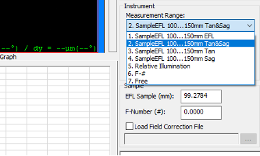
Step 9: Switch to corresponded sample EFL and wavelength under “measurement range” page, cross wire will be shown in the display area. Avantier has abundant filters in stock making sure broad range of wavelengths can be measured at this stage.
Figure 9
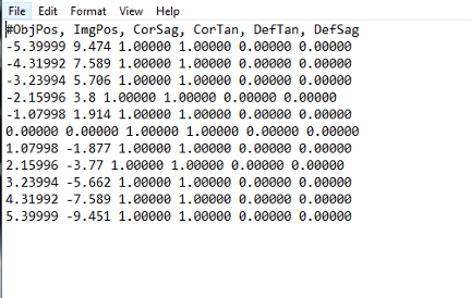
Step 10: Edit “Field Angle/Image Height” data in the txt document
Figure 10
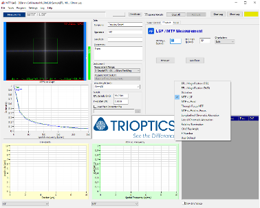
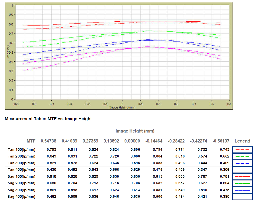
Step 11: Input corresponded line number and edited txt document under “MTF vs Field” page to generate the complete testing curve.
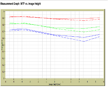
What does the MTF testing result look like?
Below are MTF plots and tables of one of our 20X customized objective lenses. With Avantier’s design and manufacturing capabilities, we can fully meet customer’s requirements, as shown in result of MTF measured at from 100lp/mm to 400lp/mm in both tangential and sagittal directions.
In summary, the objective lens MTF testing is an indispensable process at the heart of Avantier’s optical manufacturing prowess. Through rigorous MTF analysis, we gain deep insights into the true capabilities of our lenses, ensuring they meet the highest standards of contrast, sharpness, and resolution. This commitment to precision and quality defines Avantier’s dedication to delivering optical solutions that empower industries and push the boundaries of clarity and performance.