Freeform Optics: Advances and Developments
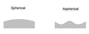
While most traditional optics have constant curvatures and are rotationally symmetric, freeform optics break all the norms. And there’s a very good reason they do.
Design flexibility and many degrees of freedom mean a freeform optic can achieve optical mapping relationships that aren’t possible with your ordinary symmetric optic. When you need optimal performance in a small package, a freeform optic can be a very good option. You’ll have fewer surfaces, less mass, and reduced stray light. What’s more, one optic can be designed to fulfill multiple optical functions in one go. Correcting aberrations, increasing depth of field and expanding field of view, all in one optical component? No problem!

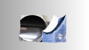
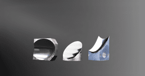
Defined as surfaces without any axis of rotational invariance, freeform optical surfaces have asymmetrical features and three or more independent axes. They may have various geometric designs and can be customized for their applications. They are more challenging to manufacture than traditional optics elements with rotational symmetry, but recent advances in manufacturing techniques are making it possible to manufacture freeform optics with greater speed and less cost than ever before.
Applications of Freeform Optics
Freeform optical surfaces are becoming important in more applications. They may be used for imaging, illumination, concentration, or manipulation of light, and they are typically designed for a specific purpose and application. One example of freeform optics in use is in the SCUBA-2 optical system within the James Clerk Maxwell Telescope in Hawaii. The original SCUBA (Submillimeter Common-User Bolometer Array) was first used in the 1990s to record thermal emissions from interstellar dust. In service till 2005, it was second only to the Hubble Space Telescope in the amount of high-impact astronomical research it enabled. The original instrument was limited by traditional optics and the optical manufacturing capabilities of its time, but its replacement, the SCUBA-2, was able to take advantage of advances in freeform optics manufacturing techniques. It included nine aluminum freeform mirrors, which give it an extra large field of view and sky background limited sensitivity. The SCUBA-2 can also inspect large areas of sky up to 1000 times faster than the apparatus it replaced.
Another example, closer to everyday life, is in the design of rearview mirrors. An ordinary rearview mirror has a very limited field of view and produces some highly problematic blindspots. When a freeform reflector is used instead, you have a mirror with a 45 degree field of view, no blind spots and very little distortion.


Developments in Design of Freeform Optics
Both the design and manufacturing of freeform optics are more complex processes than those involved in traditional optics. To begin with, there are just so many more variables! One recent development in the design and manufacture of freeform systems has been the inclusion of data surfaces and fiducials directly into the optics. A fiducial is simply a mechanical reference or physical mark placed directly on the optic. Including fiducials enables us to effectively ‘lock’ a number of different degrees of freedom, reducing them to a manageable number and enabling precision manufacturing and metrology. While traditional optics may be designed sequentially, with freeform we need to take a more parallel approach. This is called concurrent engineering and reduces the likelihood of expensive redesigns. Some factors that must be considered at the beginning of the process are required specifications for clear aperture, extended aperture, datum and fiducials which will be used to orient the part. How is the freeform to be shaped, outside the clear aperture? Some applications may require quick slope changes and other extreme shapes. While this is possible, it does give certain challenges in manufacturing. Defining a robust datum structure for the optic that can be used to reference all features is one of the first steps in designing a freeform optic. How can a freeform structure be made easier to rind, polish, measure, and align? These considerations also need to be part of the design process, to avoid running into dead ends as manufacturing processes unfold.Manufacturing Processes of Freeform Optics
The actual fabrication of the freeform typically takes place with methods of subtractive manufacturing, where CNC machine grinding, polishing, turning and milling turn substrate into the desired form. Even where molding techniques are to be used, an initial template created through subtractive manufacturing is typically necessary.
Freeform optic metrology typically uses stitching interferometry or computer generated holograms (CGHs) to produce reference wavefronts to serve as optical nulls. CGHs are generally considered the best option but can get expensive as a different CGH is necessary for each design. Very complex surfaces that cannot be measured effectively with CGHs or stitching interferometry may be measured by single-point coordinate measuring machines.
At Avantier, there’s nothing we love more than a good challenge. Manufacturing and design of freeform optics isn’t easy, but it is one of our areas of expertise and we’d love to help you bring the power of freeform to your application. Contact us today if you’d like to discuss your options or schedule an initial consult.
Related Content
GREAT ARTICLE!
Share this article to gain insights from your connections!


